Follow Up: Here’s the data that I’ve been collecting with this project
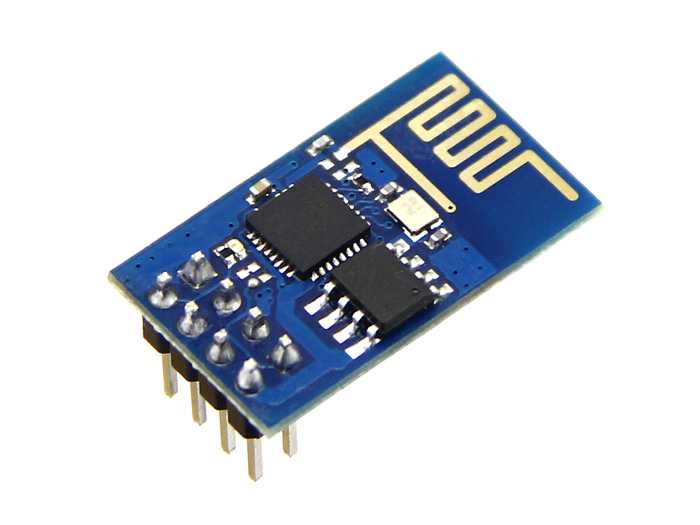
The ESP8266 has been out for a little over a year now, and even when it was first released it was making waves. $4-$5 USD cost, Wireless 802.11b/g/n, microprocessor with GPIOs and analog inputs, oh my! I was an early-ish adopter of the ESP8266 - though it always confused me exactly what I was going to do with it.
Adapting
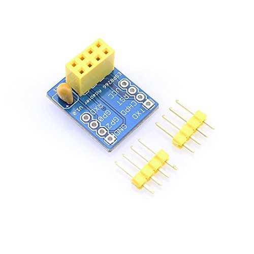
Not to mention how to build it because the ESP8266 (specifically the ESP-01) has a very odd footprint; and isn’t breadboard compatible. At least not without a special adapter. I eventually was able to build up an adapter of my own - it works pretty well. The one pictured here (which was not the one I made), was $7 USD at the time of writing. More costly than the ESP8266 board in the first place!
It’s what temperature in here?
One of my favorite applications for the ESP8266 is the wireless sensor applications - my goto is usually temperature (it’s like the Hello World of IoT). But being kind of a data nerd I enjoy anything that will collect data and store it.
Initially I had used the NodeMCU firmware on the ESP8266. It was a bit buggy, not incredibly stable, and it uses Lua as the scripting language. Very easy to upload new scripts to the device, which was certainly a plus. The NodeMCU firmware has matured quite a bit since it’s initial release. I ultimately prefer using the Arduino IDE, but NodeMCU is a viable option.
Recently, the Arduino IDE has started supporting the ESP8266 boards. This allows you to use the Arduino libraries on the ESP8266, along with using the Arduino programming language (which is really just C). This makes integrating with other devices, like ones that are already supported on the Arduino platform fairly trivial.
Sensing things
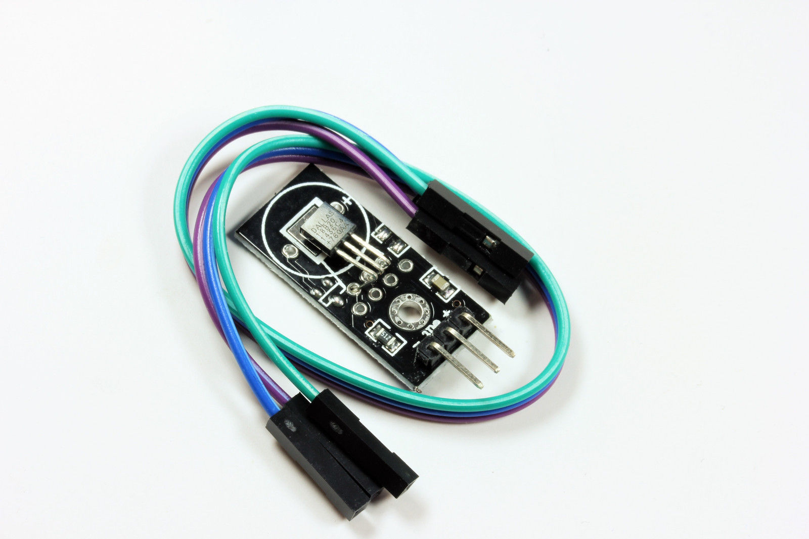
For this project I was going to integrate a DS18S20 - a OneWire Temperature sensor, with the ESP8266 and have it report the temperature to an endpoint at a configurable interval. The endpoint should be an arbitrary web endpoint - something similar to ThingSpeak or data.sparkfun.com (which is a hosted version of their open source software Phant).
Putting it all together
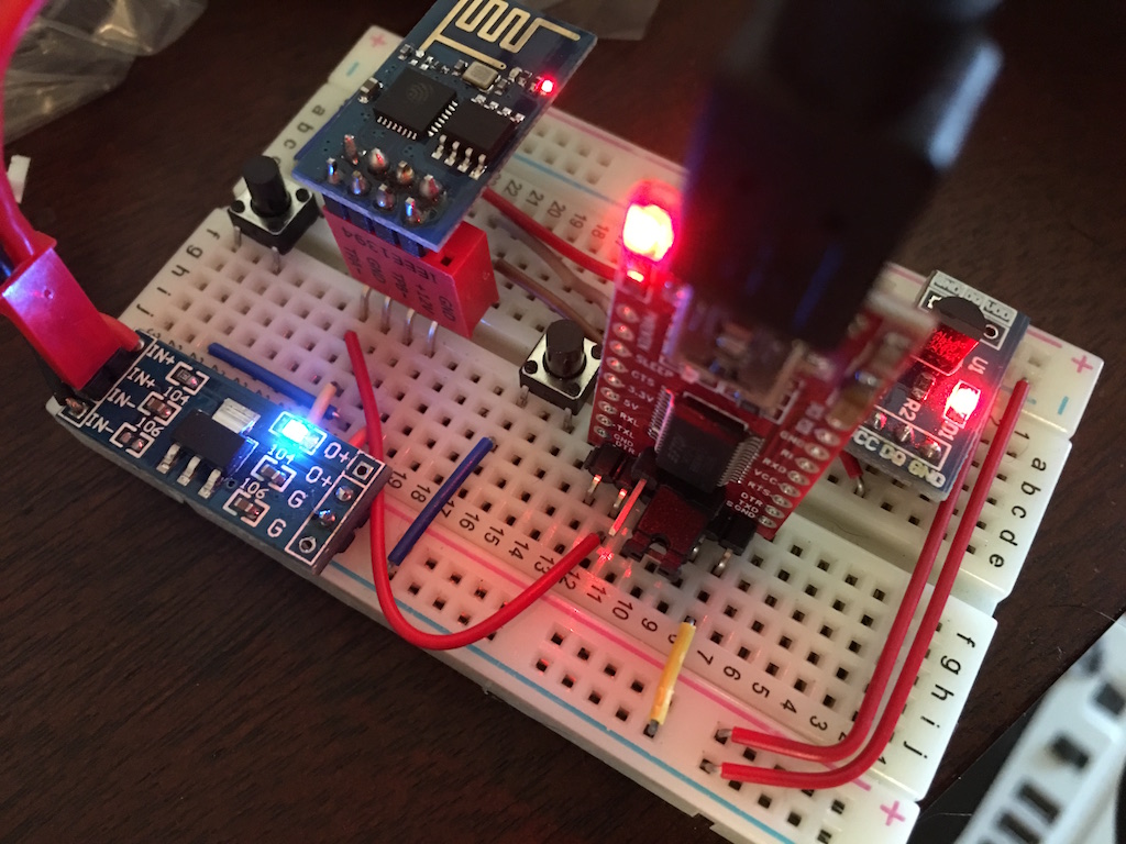 From bottom left: 3.3v regulator, ESP8266 - ESP-01 version, USB FTDI Cable, DS18S20 Breakout Board. Reset button is on the left, GPIO 1 / programming button is on the right
Using some pre-assembled modules made this process significantly simpler to deal with. On the breadboard I have a 3.3v regulator like this which is good to up to 800ma @ 3.3v, and can accept voltage up to 6-9v (I typically run it at 6v). These little chips tend to be power hungry. I’ve heard people say they’ve pulled up to 300ma while transmitting; if you’re ever running into problems with your ESP8266 the first troubleshooting step you should take is checking on your power supply.
I’ve got a trusty FTDI USB Adapter - it runs at either 3.3v or 5v (using 3.3v for the ESP8266 as it is not tolerant of voltages above 3.3v). This allows me to communicate with the ESP8266 via Serial.
Also wired up a couple of buttons to my ESP8266, reset and GPIO 1. Both of these are required for getting the ESP8266 into programming mode. You reset the ESP8266 and hold the button connected to GPIO 1 (which we have tied to ground, thereby pulling GPIO 1 “low”) to kick the ESP8266 into programming mode for flashing.
A better future
Now a days (at least at the time of writing) there are much newer versions of the ESP8266, that break out more pins, are breadboard compatible, handle power conversion, and also USB to Serial conversion. They even automatically hop into programming mode. But I was an early adopter of these things, and I enjoy doing stuff the hard way sometimes. I plan on writing more posts about the newer modules later. If you’re interested in these modules, I’d suggest the newer ones.
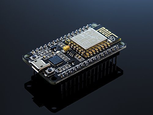
The latest ESP8266 that I’ve purchased. Link
Some code with a side of explanation
Below is the code that I’m using to send the temperature of my apartment to the internet every 10 minutes. I wrote this code and flashed it to my ESP-01 by using the Arduino IDE.
Thank goodness for libraries. This code currently does not use the Dallas Temperature Control library which would make this even easier to read and understand. The only real complex portion of this code is reading from and writing to the OneWire temperature sensor. Mainly instructing the sensor what we need it to do next. The implementation here was taken from the example files for the DS18x20 sensor libraries on Arduino.
The code isn’t overly complex. It connects to wifi initially, then every 10 minutes it reads the sensor, gets back the temperature (in celsius), converts it to fahrenheit, and then sends the value to data.sparkfun.com.
I track the interval by checking the output of millis() instead of using delay(), this frees up the microprocessor to do other things in between sends. If you were running this sensor off battery, you’d want to deep sleep here.
Go Build something
I hope you enjoyed learning about the ESP8266 as much as I have, for future plans I’ve got a few different applications in mind.
- More temperature sensors, even an outdoor one.
- Wirelessly controlled relay
- Humidity / Temperature sensor - for the bathroom
- Outdoor weather station. Might need more GPIOs for that one!